I still have not been able to confirm the status of the MSP430G2 LaunchPad. At TI website it's still marked active and I was able to order some today, although their confirmation e-mail is non-committal:
"You will receive an e-mail within 24 hours that includes the estimated shipping date for in stock items, or a backorder date for products not currently available. Once these items are packed and ready to be shipped from our warehouse, you will receive a shipping notification with the carrier name and tracking number of your item(s). Your credit card will not be charged until we ship the item(s) to you. If you would like a real time status of your order, please visit your personal My Account Page."
I checked my TI account and it shows my order for LaunchPads will ship on 11/21. I just rechecked the TI store and the MSP430G2 LaunchPad is listed as a top seller (Yea!) and it's still in the list of LaunchPads.
The distributor Newark (Element14) has over 300 in stock and clicking their check additional stock link indicates that they expect more on Dec. 2. However their link for the Stellaris LaunchPad indicates that when current stock runs out there will be no more. Element14 has been a proponent of the LaunchPad so I would expect them to be plugged into what is happening, so I feeling more assured.
I'm feeling better about the LaunchPad than I was this morning, but I wish that I could get confirmation from TI. I have never been able to find a "Contact Us" link on the TI website so I cannot contact the LaunchPad's manager directly. Maybe a post on their forum is in order.
Stay tuned!
Monday, November 18, 2013
Oh No!
I visit TI's web sites a lot searching for information about the LaunchPad. Therefore, thanks to Google's omnipresent tracking, I get pop-up ads in sidebars hawking TI products. Today I got one for the "All New" MSP430 LaunchPad. I clicked on it with trepidation and was taken to a site with TI's all new lineup of development boards.

The new MSP430 Launch Pad has a soldered-in-place processor, a double row of header pins on both sides. You can find the new LaunchPad here: http://www.ti.com/tool/msp-exp430f5529lp The "All New" price is $12.99. This development is distressing for a number of reasons. It's not clear if the old LaunchPad will be discontinued. The new LaunchPad abandons the header arrangement of the old version and adopts the style of the Stellaris LaunchPad at least physically (I cannot determine if the pinout is the same). That means any booster packs designed for the old LaunchPad have a limited future.
The new LaunchPad claims to have USB and a faster clock, more I/O and a higher resolution on the analog to digital converter. However, most of these will be overkill for the simple tasks that we have on model railroads (the exception may be Dave Loman's JMRI to LaunchPad interface). For $12.99 the Stellaris LaunchPad - which features a true ARM processor - may be the better deal. The non-removable processor prevents exchanging the processor for a different type and it prevents removing a processor after programming for use on a dedicated PCB. And, while the $12.99 price is still one of the cheapest microcontroller boards around, it's a far cry from the $4.30 where the LaunchPad started.
If you search the TI site for MSP430 LaunchPad, you'll be directed to the new version. However, the old version can be ordered here:
http://www.ti.com/tool/msp-exp430g2?DCMP=hpa_bestbets_estore&HQS=estore-tool-bb-launchpad
I blasted out an order for myself (I've been using a lot of these in my LaunchPad for Model railroading clinic). I checked Mouser and Digikey who still have many in stock. I did not check Farnell or any of the overseas distributors. From how quickly these sell, I'm sure that we are not the only community building these boards into permanent projects. If you want some of the older version, I suggest that you get them now, in case the version that we know and love is discontinued.
I'm going to see if there is someone at TI to whom we can appeal to save the old LaunchPad, if indeed it is going to be discontinued. The LaunchPad design files are available, so more could be built. But this would be a capital intensive project as they would have to be built in the thousands for the price to be anywhere near $10.
Stay tuned!
Wednesday, November 13, 2013
Jim Gifford's Grade Crossing V1.0
Moderator's Comment: Here's a project that illustrates integration of a LaunchPad with other commercial products to implement a grade crossing flasher with bell sounds.


Grade
Crossing V 1.0
This
project uses a Launchpad to drive relays that operate the globe based crossing
signals for a double track main with individual track current sensors and the
need to sense any equipment that does not draw current that is over the crossing.
The
givens are: crossing globes operate on 8-10V, relays operate on 12V, Block
Watchers used for signal logic (switched output [J4]) operate on 12V but not on
a common ground with rest, it is a double track crossing and needs IR detector
at crossing to detect train without resistor axles (covers situation when locos
of train have exited the power block leaving nothing to be detected by the
Block Watcher).
I
have built my own power supply board that utilises one of my 18V 4 Amp AC
accessory power circuits and outputs 12V & 5V regulated DC. I drive the lamps from the 12V through four
diodes to drop the voltage to just under 10V.

In
this project a LaunchPad, powered from the 5V regulated power supply, will
control the (3) 12V Relays by monitoring the state of the switched outputs (J4)
of two DCC Specialties Block Watchers providing track occupancy coupled with IR
detection across the double track crossing operates the two sets of crossing
lights and a sound module until a predetermined time is reached after all
inputs are restored to an inactive state.
The crossing should operate if Track1 occupied, Track 2 occupied or the
IR sensor is active.
Bill of Materials:
(1) 1 x LaunchPad with MSP430G2553IN20 processor.
(1) 1 x LaunchPad with MSP430G2553IN20 processor.
(2)
1 x 4 way relay board ( this link
).
(3)
2 x switched output e.g. (J4) DCC Specialties Block Watcher ( link ) .
(4)
1 x 3mm Infrared phototransistor ( link
).
(5)
1 x 3mm Infrared diode ( link ).
(6)
1 x 150Ω ¼W resistor.
(7)
2 x Optocoupler ( link
)
(8)
1 x Innovative Train Technology Products HQ300-1 Grade Bell ( link )
(9)
1 x Innovative Train Technology Products 4" - 8Ω Speaker SPKR4 ( link )
(10)
1 x Power supply (see below)
Notes:
(1)
remember to include a resistor to limit the current in the block watcher
circuit to protect the LED embedded in the optocoupler.
(2)
( links ) were valid at the time of publication.
Power
supply bill of materials:
(1) 8 x 1N4001
Diodes.
(2)
1 x LM7812CT 12 Volt Regulator
(3)
1 x LM7805CT 5 Volt Regulator.
(4)
1 x 1000µf 50V.
(5)
2 x 10µf 50V.

1 - Block Watcher

2 - Power Supply

3 - Quad Relay

4 - Sound Module

5 - Putting it all together
(Ammeter
& Voltmeter included on power supply board)

6 - IR sensors mounted in PVC tubes (painted black)

7 - Scenery added (white glue applied)
Theory of Operation:
The Power on LED is connected to pin P1.0 and illuminates when the LaunchPad is running the program.
The Power on LED is connected to pin P1.0 and illuminates when the LaunchPad is running the program.
The switched output
of each Block Watcher (J4) is connected to the LaunchPad via an optocoupler switching
VCC to pins [Board (IC)] P2.0 & P2.1. When a train is detected by a Block Watcher
and its switch (J4) is closed the optocouplers operates and causes their
respective pins to go "high" and the software in the LaunchPad causes
relays 2 & 3 to turn on and relay 1 to cycle off and on for a predetermined
time. Similarly if the IR sensor goes
"high" it has the same result.
This
is achieved by monitoring 3 inputs: Block Watcher 1 - P2.0; Block Watcher 2 - P2.1;
IR sensor - P2.2. If any or all of the inputs go high: set Inputs_Active (flag)
to 1 and cycle light sequence 5 times with the sound module activated. This is achieved by: setting P1.6 to ON (Light
power); setting P1.7 to ON (Sound power); and cycling P1.5 ON & OFF 5
times. If any input (P2.0, P2.1 or P2.2)
remains high then the sequence is repeated.
Circuit
Diagram:
While the diagram looks complicated, hookup is actually reasonably simple using wire wrap techniques. It is good practice to solder wire wrapped joints for long term reliability once testing is complete.
While the diagram looks complicated, hookup is actually reasonably simple using wire wrap techniques. It is good practice to solder wire wrapped joints for long term reliability once testing is complete.

Demonstration of the Prototype
Link to Video of
prototype operation.
Link to Video of testing
before installation
Demonstration of the Installation
Link to Video of IR
operation.
Link to Video of Block
& IR operation.
The
Code
The
code can be found here.
The
code listing follows below.
/*
*
Grade Crossing 1.0
*
COPYRIGHT © 2013 Jim Gifford
*
http://halletcovesouthern.blogspot.com.au
*
Provided under a Creative Commons Attribution, Non-Commercial Share Alike,3.0
Unported License
*
*
I wish to acknowledge code snippets initially written by:
*
“Steve Hoffy Hofmeister” & “Terry Terrance”
*
*
TARGETED TO MSP430 LANUCHPAD W/MSP430G2553N20 PROCESSOR
*
*
Design Notes:
*
*
This code is designed to receive an input from either of 2 DCC Specialties Block
Watchers and a IR LED/Phototransistor Sensor pair that turns on the power to
light Crossing lights via a relays, turn on a sound module and hold them on for
a predefined period of time (currently set to about 3 seconds) after detection
ceases.
*
*I
have built my own power supply board that utilises one of my 18V 4 Amp AC
accessory power circuits and outputs 12V & 5V regulated DC. I drive the lamps from the 12V through four
diodes to drop the voltage to just under 10V. I have connected the MSP430 to
the 5V regulated supply.
*
*
*
Circuit Pinout:
*
PIN 1.0 = Circuit Power Indicator
*
PIN 1.1 = UNASSIGNED - UART
*
PIN 1.2 = UNASSIGNED - UART
*
PIN 1.3 = UNASSIGNED
*
PIN 1.4 = UNASSIGNED
*
PIN 1.5 = Relay 1 Trigger
*
PIN 1.6 = Relay 2 Trigger
*
PIN 1.7 = Relay 3 Trigger
*
PIN 2.0 = Input for Block Watcher 1
*
PIN 2.1 = Input for Block Watcher 2
*
PIN 2.2 = Input for IR sensor
*
PIN 2.3 = UNASSIGNED
*
PIN 2.4 = UNASSIGNED
*
PIN 2.5 = UNASSIGNED
*
PINS 1.1, 1.2, 1.3, 1.4, 2.3, 2.4 & 2.5 are left unused for integration
into other projects.
*
Note Anodes for the IR Emitter connect to VCC and Cathode to Ground
*/
#include
<msp430g2553.h>
/////////////////////////////////////////////
// Define variables
////////////////////////////////////////////
volatile
unsigned long Relay_1_Timer = 30000;
//Define time for outputs to stay on
volatile
int Active = 0;
volatile
int Inputs_Active = 0;
volatile
unsigned long Counter = 0;
//
delay macros
#define
DELAY_FLASHER(delay) doDelayFlasher(delay)
//
routine definitions
void
doDelayFlasher(unsigned long delay);
void
main(void) {
WDTCTL = WDTPW + WDTHOLD; // Stop watchdog timer
P2OUT = 0; // Set All P2 to Off
//Configure
Outputs
P1DIR |= BIT5; //
Port P1.5 (Relay 1 Trigger) as output
P1OUT &= ~BIT5; //
Port P1.5 (Relay 1 Trigger) Set to off State
P1DIR |= BIT6; //
Port P1.6 (Relay 2 Trigger) as output
P1OUT &= ~BIT6; //
Port P1.6 (Relay 2 Trigger) Set to off State
P1DIR |= BIT7; //
Port P1.7 (Relay 3 Trigger) as output
P1OUT &= ~BIT7; //
Port P1.7 (Relay 3 Trigger) Set to off State
//
Configure Inputs
P2DIR &= ~BIT0; //
sets Port 1, bit 7 to input from Blockwatcher
P2OUT &= ~BIT0; //
sets pull-up resistor on Port 1, bit 7 to pull-up
P2REN |= BIT0; //
pull up bit0
P2DIR &= ~BIT1; //
sets Port 1, bit 7 to input from Blockwatcher
P2OUT &= ~BIT1; //
sets pull-up resistor on Port 1, bit 7 to pull-up
P2REN |= BIT1; //
pull up bit1
P2REN |= BIT2; //
Port 2 Resistor enable
P2OUT |= BIT2; //
pull up bit2
//
Show Launchpad Active
P1DIR |=
BIT0; // Circuit Power Indicator
P1OUT |=
BIT0; // sets Port 1, bit 0 to on - use onboard LED
//
Let's Get Down to Business
while( 1 ) // begin
infinite loop
{
// Do while any of 3 inputs are
active
// 1 Block
Watcher 1 (J4 closes & goes high) P2.0
// 2 Block
Watcher 2 (J4 closes & goes high) P2.1
// 3 IR
sensor detection active (goes high) P2.2
// & if so activate the
crossing signals
if ( ((P2IN&BIT0) == 0)
&& ((P2IN&BIT1) == 0) && ((P2IN&BIT2) == 0) ) // No inputs active
{
// Set to Relays
to off
P1OUT &=
~BIT5; // Port P1.5 (Relay 1 Trigger)
Set to off State
P1OUT &=
~BIT6; // Port P1.6 (Relay 2 Trigger)
Set to off State
P1OUT &=
~BIT7; // Port P1.7 (Relay 3 Trigger)
Set to off State
}
else // At least 1 input active
{
Inputs_Active =
1;
while
(Inputs_Active < 6) // Go through 5
cycles
{
//
Start crossing working
P1OUT
|= BIT6; //
Set Relay 2 Trigger to ON - Light power
P1OUT |= BIT7; // Set Relay 3 Trigger to ON -
Sound power
DELAY_FLASHER(Relay_1_Timer); // Let lights 1 stay on for value of
Relay_1_Timer
P1OUT
|= BIT5; //
Set Relay 1 Trigger to ON
DELAY_FLASHER(Relay_1_Timer); // Let lights 2 stay on for value of
Relay_1_Timer
P1OUT
&= ~BIT5; // Set Relay 1 Trigger to OFF
Inputs_Active
++; // Index the counter
} // End of input detected While
} // End of Input(s) active if
} //
End of While (while( 1 ))
} // END OF MAIN
//
Function Delay_Flasher
void
doDelayFlasher (unsigned long x)
{
Counter
= 0;
while
(Counter < x)
{
Counter ++; // Index the counter
}
}
Tuesday, November 12, 2013
GUIs, GUIs Everywhere
When I was giving the LaunchPad for Model Railroading clinic at the NMRA MER Convention in October, I mentioned that I wanted to come up with a GUI (Graphical User Interface) to enable the LaunchPad to be programmed graphically, without having any knowledge of the "C" programming language. I lamented that this project would have to wait until after I retired because I did not have the time to devote to it right now.
Well, you and I may not have to wait that long. I've recently come across several GUIs, either complete or under construction, that allow you to manipulate a LaunchPad without having to program in "C". These GUIs allow you to manipulate a LaunchPad while it is connected to your computer (rather than what I wanted, which would program the LaunchPad to operate stand-alone). However, they are still useful for model railroading purposes and one of them, being built by Dave Loman, allows you to manipulate a LaunchPad using JMRI.
First, here's a link to Dave's work: http://therustyspike.com/2013/11/05/cmri-emulation-on-a-mps430/ This GUI holds the most promise for model railroaders. When it is finished, JMRI will be able to manipulate your LaunchPad. With it JMRI should be able to turn pins on and off. This will allow the LaunchPad to manipulate signals, switches and other accessories allowing it to be part of JMRI's Panel Pro application.
I stumbled across two other GUIs written by hardware hackers to allow them to manipulate a LaunchPad while connected to a computer. Both are available via TI's E2E website. First is ControlWare: http://e2e.ti.com/group/microcontrollerprojects/m/msp430microcontrollerprojects/665272.aspx The second is ControlEasy:
http://e2e.ti.com/group/universityprogram/students/m/students_repository/664591.aspx
These GUIs add the capability to generate PWM (Pulse Width Modulation) which allows for blinking lights and servo control. Both of these GUIs also require that the LaunchPad is connected to your computer to work. This is not as much of a disadvantage as one might expect. If you want to manipulate things connected to your LaunchPad in real time, you can do so now from a computer. Want to be able manually throw a turnout, change a signal, move a servo; you can do it from your computer.
There are demonstration videos for both of these on the TI website. I have tried neither of these latter two GUIs, documentation is sparse and they may be difficult to install. ControlEasy was written by a student. I'm hoping that the source code for these will be released so that when I start my GUI, I can reuse some of their work.
If you give either of these a try, let us know how they work out.
Wednesday, October 2, 2013
Two Way Infrared Beam Detected Speed Trap with LCD Display
Wow, I can not believe it has been so long since I have contributed to the Launchpad for Model Railroading Blog. It seems only weeks ago Terry opened up this wonderful can of worms to the model rail community.
I wanted to take a quick moment to apologize for the loss of content on my previous contributed posts to this blog. I suffered a major hard drive failure during the revision of my main website which caused a loss of several thousand files from my archives, among these were the backups of these missing images. I just recently discovered they were missing on this blog. I have been working to recover or redevelop these images and will be revising those posts soon.
Now, on with the show.
This project is a bi-directional speed clocking or "Speed Trap" to display the scale speed of a passing train. bi-directional means that it will work regardless of the direction the train is traveling on the track.
How does it work?
The train is detected by the use of Infrared Beam Detection or otherwise know as an Interrupters. The train passes through two sets of detectors containing a Infrared Emitter and a Infrared Detector, when the nose of the train breaks the beam between these two components the time count starts that will be used to calculate the speed. The specific calculation is adjustable by scale such as 160 = N Scale, etc. When the nose of the train reaches the second set of the detection components the counter stops and the code quickly calculates the speed.
The distance between the detector components is also entered into the code as well. The default is set to 12 inches, but can easily be changed by replacing the 12 with another inch measurement.
This particular variation of this code uses an 16 Character, 2 line Liquid Crystal Display "LCD" to show the state of the "Speed Trap" and the calculated speed. Below is a video demonstration of the prototype showing the functions.
New Video Posted as of 7/5/2015 \/


Because there are multiple required files and libraries for this project to compile, a code snippet as been intentionally left out of this post
You can obtain the code, instructions, and schematics at hoffysworld.com
I wanted to take a quick moment to apologize for the loss of content on my previous contributed posts to this blog. I suffered a major hard drive failure during the revision of my main website which caused a loss of several thousand files from my archives, among these were the backups of these missing images. I just recently discovered they were missing on this blog. I have been working to recover or redevelop these images and will be revising those posts soon.
Now, on with the show.
This project is a bi-directional speed clocking or "Speed Trap" to display the scale speed of a passing train. bi-directional means that it will work regardless of the direction the train is traveling on the track.
How does it work?
The train is detected by the use of Infrared Beam Detection or otherwise know as an Interrupters. The train passes through two sets of detectors containing a Infrared Emitter and a Infrared Detector, when the nose of the train breaks the beam between these two components the time count starts that will be used to calculate the speed. The specific calculation is adjustable by scale such as 160 = N Scale, etc. When the nose of the train reaches the second set of the detection components the counter stops and the code quickly calculates the speed.
The distance between the detector components is also entered into the code as well. The default is set to 12 inches, but can easily be changed by replacing the 12 with another inch measurement.
This particular variation of this code uses an 16 Character, 2 line Liquid Crystal Display "LCD" to show the state of the "Speed Trap" and the calculated speed. Below is a video demonstration of the prototype showing the functions.
New Video Posted as of 7/5/2015 \/
Credit to Toni Ryan for the development of the speed calculation and timing for this project.
For those new to the Launchpad for Model Railroading group-source adventure, I consider this to be an "Advanced" project. You will never read of my describing this as "Difficult" or "Complicated" on this blog because at the source of it all, it is really quite easy to set up. I choose the word "Advanced" as more extensive skill in electronics make this particular project much easier to understand and implement. Also, please do not be alarmed by the spaghetti of wires shown in the diagrams below, they are quite straight forward in the connections.
Now let's discuss the parts needed:
The Red and Green LEDs mimic the Red and Green LEDs built on the MSP430 Launchpad. These external LEDs are not required for operation but were added for the demonstration.
2 - 10 Kilo-Ohm "K" Potentiometers - you can usually find these easily online and vary in style. A particular style is not required as long as the are 10 Kilo-Ohm "K". These are used to control the brightness and contract of the LCD display.
2 sets - IR Emitter / Detector Pairs - these are easy to pick up at your local "Radio Shack" or equivalent electronics retailer. Most electronics supply stores or website carry these as well.
1 16 x 2 Liquid Crystal Display "LCD" Color choice is builder's preference as they come in multiple styles.
A note about the LCD in this project.
The LCD I used in this project requires a 5 Volt power source. You can use the 5 Volt source that comes through the USB connection to power these displays, or an external 5 volt power source. There are 3.3 Volt versions on the market which can be connected to the Vcc and Gnd connections on the launchpad to get power. DO NOT try to power a 5 Volt LCD from the 3.3 Volt Vcc connection. It will not work and may damage your hardware.
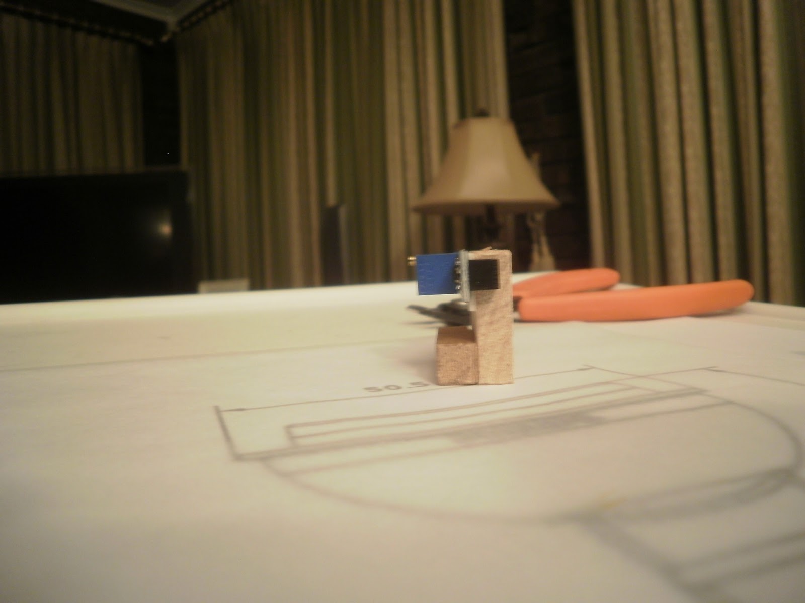
To use the 5 volts supplied by the USB, you need to add some connection points to your launchpad with a soldering iron.


As you can see from the photo above. I soldered two single pin connections to my Launchpad. You could solder wires directly to these same points, but I chose to use these so I can connect wires from my development breadboard to the power source.
I would not advise powering anything more than the LCD from this 5 Volt Source, as USB power can be very finicky depending on the hardware driving it.
Diagrams:
IMPORTANT NOTE:: Please Review my previous project Quad IR Beam Detector to better understand how the IR IR Emitters and Detectors are connected, and the theory behind how they work. Connecting the IR Detectors wrong will damage them. Please verify your connections before applying power.


Because there are multiple required files and libraries for this project to compile, a code snippet as been intentionally left out of this post
You can obtain the code, instructions, and schematics at hoffysworld.com
Project Schematics and Breadboard image updated to correct errors on 7/5/2015
Thursday, July 25, 2013
Live and Learn
Several interesting things happened during the build-up to and the execution of the clinics that I gave at the NMRA national convention.
My work and travel schedule dictated that I had to postpone wiring the 3-color signals on the demonstration diorama until I was actually in Atlanta the day before my clinic. As I started to wire the 3 additional LaunchPads that operate the signals to the 3 optical detectors, squirrely things started to happen. Long story short (and I'm ashamed to say) that I had made an amateurish mistake in the electrical design and layout of the diorama. I had too many signals hooked up to each optical detector. This problem is called "fan-out" in electronics and I should have known better. You are not likely to encounter a fan-out problem in routine working with the LaunchPad. My problem arose because I was trying to fit too many effects into the one diorama that led to too many LaunchPads connected to each optical sensor.
This led to another realization that I should have avoided. The effects on the diorama were so interconnected that if anything failed it would prevent almost all of the effects from working. This is called single-point failure and, as a long-time avionics system engineer, this is something I look for in my professional designs. I just never applied it to my hobby pursuits.
I could have fixed the problems; if I were at home and had access to my stock of electronics parts. But seeing as I was in a hotel room in Atlanta, I decided that the best that I could do was not to hook up the signals. However, single point failure was not done with me yet.
The diorama worked perfectly in the hotel Thursday and Friday in the morning before I went to do my first clinic. After I set up in the clinic room almost nothing was working! WTF? After some abbreviated troubleshooting, I lifted up the diorama and saw that one of the optical sensor's LED was constantly illuminated indicating that the sensor was stuck in the "on" state. Quickly going through a fault tree mentally, I realized that with the one sensor stuck "on", nothing but the crossing flasher would work; and I'd have to trigger that effect manually by putting my finger over one of the other sensors. Single point failure had struck again! So for my first clinic the diorama was a washout.
I thought that it was a simple matter of the sensitivity potentiometer being knocked out of adjustment by all of the travel. So before my next clinic, which was that evening, I disassembled the diorama to adjust the screw, which I did. When I powered it back up to my surprise all of the optical sensors were now stuck on! At this point I was beginning to believe in demonic possession (especially since that had been a topic in the previous Sunday's sermon!). Now I was really perplexed.
I wracked my brain for an answer. In examining the diorama I turned it sideways - and all of the sensors turned off! Then I had a flash of insight. In a scene reminiscent of one from the movie "Aliens" I looked up towards the ceiling. There was a hot incandescent spotlight directly overhead. The incandescent bulb was emitting just enough infrared light to trigger the sensor. I realized that I had never tested this sensor under incandescent light - it had always been used under the ubiquitous florescent lights. I went to the clinic room's light switch and turned off the offending bank of lights. Everything worked perfectly.
So the second clinic had a working diorama by the simple expedient of turning off the room light in the front of the clinic room - which also made the slides easier to see.
Fan-out, single point failure, inadequate testing - all things I should have known better. Duh! Live and learn.
Jim Gifford's Quintet Optical Sensor
Here's a project from Jim Gifford (Hallet Cove Southern) from "Down Under" which illustrates the best of the open source paradigm. Jim has taken parts of other projects posted here, merged them and re-purposed them to create a rather nifty project. This is what open source is about - reuse and innovation!
Jim has used a pair of LaunchPads, LEDs and optical detectors to detect the trains in his five-turn helix. Here's Jim's description:


(1) 2 x LaunchPad with MSP430G2553IN20 processor.


Reflective optical sensors are placed adjacent to the track at predetermined locations on the helix.


When a train is detected, the software in the LaunchPad causes the respective output to go high (turn on) and stay illuminated for a predetermined time.
Remember two of these circuits are required to illuminate the 10 LED’s. While the diagram looks complicated, hookup is actually reasonably simple using wire wrap techniques.

Jim has used a pair of LaunchPads, LEDs and optical detectors to detect the trains in his five-turn helix. Here's Jim's description:
Quintet
Optical Sensor
This
project is to sense movement of a train through my helix. The single
track helix has a 33” radius and has approximately 5 ½ turns – HO scale 95 feet
of track – so I have decided 10 detectors are required each having an output which
stays on for around 10-12 seconds so that progression of a single railcar can
be seen on a “row of LED’s” display.

In
this project two LaunchPads will control the 10 LED display. Each
LaunchPad reads five of the optical sensors providing track occupancy and then illuminates
respective LED’s for a predetermined time. Please note that the “Block
Occupied” indication comes from a “Block Watcher” detector to be used for
signal logic.
Proposed Indicator
Panel

Bill of Materials:
(1) 2 x LaunchPad with MSP430G2553IN20 processor.
(2)
10 x Optical sensor modules from a Chinese vendor IR Reflective Sensor (this link
was valid at the time of publication) .
(3)
6 LED’s per LaunchPad.
(4)
5V regulated power supply to supply the optical sensors.

Optical
Sensor - component side of board

Optical
Sensor - emitter/detector
side of board
Theory
of Operation:
Reflective optical sensors are placed adjacent to the track at predetermined locations on the helix.

Each set of five sensors are connected to pins [Board
(IC)] P1.0 (2), P1.3 (5), P1.4 (6), P1.5 (7), P1.6 (14) and the respective indicator LED’s are
connected to pins P2.0 (8), P2.1 (9), P2.2 (10), P2.3 (11), P2.4 (12) of the
LaunchPad.
When a train is detected, the software in the LaunchPad causes the respective output to go high (turn on) and stay illuminated for a predetermined time.
This is achieved by using a simple counter for
each Input/Output pair e.g. Input #1 P2.0 (input) and P1.0 (output) [Output_1_Timer]. The other pairs are P2.1/P1.3 [Output_2_Timer], P2.2/P1.4 [Output_3_Timer], P2.3/P1.5 [Output_4_Timer] and P2.4/P1.6 [Output_5_Timer]. When an input is detected
the respective counter is indexed by 1. If a long train is used it would be
possible that all detectors are indexed at the same time. If the value of a
counter is equal to 1 then the respective output is switched on. The program then
checks to see if the counter exceeds the value of the variable max_time. When the value of max_time is exceeded then the respective output in turned off and
the respective counter reset to zero.
The final check is to index the respective counter for the next
iteration of the while loop then the program keeps cycling at the chip
operating frequency which depends on supply voltage as described on page 21 of the
manual.
The
Power on LED is connected to pin P2.5 (13) and illuminates when the LaunchPad
is running the program.
Notes on setting the sensitivity
of the detectors
- Turning
the adjustment screw continuously clockwise increases the sensitivity
eventually it detects nothing but activates (output goes low) make sure
that the adjustment screw is backed off at least one turn or spurious
activation results.
- The
surface the “reflection” is sought from does matter good results where
found with white, grey, orange, with varied results from dark brown &
black.
- Direct
sunlight will activate (output goes low) the sensor.
Circuit
Diagram:
Remember two of these circuits are required to illuminate the 10 LED’s. While the diagram looks complicated, hookup is actually reasonably simple using wire wrap techniques.

The
only complication comes in the fact that the relays and optical sensors require
5 VDC. Remember that the LaunchPad runs on 3.3 VDC, so it cannot supply 5
VDC for the other modules. An external 5VDC source is wired to the relay module
and to the optical sensors. For the circuit to work with the LaunchPad
running from (potentially) a different power
supply, a common ground connection must be made between the 5 VDC supply and
the LaunchPad and it's 3.3 VDC supply. Run a wire from the GND pin on the
LaunchPad to make a connection with the GND (-) wire from the 5 VDC
supply. The LaunchPad may be powered via it's USB port (as I did) or from
an external 3.3 VDC supply.
Demonstration of the Prototype
Link to Optical sensor
testing – note detector 4 fails….
Link to testing with
minimal time delay.
Link to see final
configuration.
The
Code
The
code can be found here.
The
code listing follows below.
/*
*
Quintet Optical Sensor Version 1.1
*
COPYRIGHT © 2013 Jim Gifford
*
http://halletcovesouthern.blogspot.com.au
*
Provided under a Creative Commons Attribution, Non-Commercial Share Alike,3.0
Unported License
*
*
I wish to acknowledge code snippets initially written by:
*
“Steve Hoffy Hofmeister”
*
“Terry Terrance”
*
that were adapted for use.
*
*
Also thanks to Toni Ryan for his clarity advice
*
*
TARGETED TO MSP430 LANUCHPAD W/MSP430G2553 PROCESSOR
*
*
Design Notes:
*
*
This code is designed to receive inputs from 5 Optical Sensors and light 5
independent indicator LEDS, hold them on for a predefined period of time
(currently set to about 12 seconds), to signal that an object as been detected.
*
*This
Project has been designed to be powered by the USB connection. Consult other
available instructions on how to connect your MSP430 to external power sources
before attempting.
*
*
*
Circuit Pinout:
*
PIN 1.0 = Anode of Indicator LED #1 \
*
PIN 1.1 = UNASSIGNED - UART
*
PIN 1.2 = UNASSIGNED - UART
*
PIN 1.3 = Anode of Indicator LED #2 \
*
PIN 1.4 = Anode of Indicator LED #3 \ Cathodes to ground
*
PIN 1.5 = Anode of Indicator LED #4 /
*
PIN 1.6 = Anode of Indicator LED #5 /
*
PIN 1.7 = UNASSIGNED
*
PIN 2.0 = Input for optical sensor 1
*
PIN 2.1 = Input for optical sensor 2
*
PIN 2.2 = Input for optical sensor 3
*
PIN 2.3 = Input for optical sensor 4
*
PIN 2.4 = Input for optical sensor 5
*
PIN 2.5 = Circuit Power Indicator
*
PINS 1.1, 1.2, 1.7 are left unused for integration into other projects.
*/
#include
<msp430g2553.h>
/////////////////////////////////////////////
// Define variables
////////////////////////////////////////////
volatile long Output_1_Timer
=0; //Define Output_1_Timer &
set to 0
volatile long Output_2_Timer
=0; //Define Output_2_Timer &
set to 0
volatile long Output_3_Timer
=0; //Define Output_3_Timer &
set to 0
volatile long Output_4_Timer
=0; //Define Output_4_Timer &
set to 0
volatile long Output_5_Timer
=0; //Define Output_5_Timer &
set to 0
volatile long
max_time=100000; //Define time for
outputs to stay on
void
main(void) {
WDTCTL = WDTPW + WDTHOLD; // Stop watchdog timer
P2DIR |= BIT5; //
Circuit Power Indicator
P2OUT |= BIT5; //
Used to Trouble Shooting
//Configure
Optical Sensors
P2DIR &= ~BIT0; // sets Port 2, bit 0 to input for optical detector1
P2DIR &= ~BIT1; // sets Port 2, bit 1 to input for optical detector2
P2DIR &= ~BIT2; // sets Port 2, bit 2 to input for optical detector3
P2DIR &= ~BIT3; // sets Port 2, bit 3 to input for optical detector4
P2DIR &= ~BIT4; // sets Port 2, bit 4 to input for optical detector5
P2REN |= BIT0; // sets pull-up resistor on Port 2, bit 0 input pin
P2REN |= BIT1; // sets pull-up resistor on Port 2, bit 1 input pin
P2REN |= BIT2; // sets pull-up resistor on Port 2, bit 2 input pin
P2REN |= BIT3; // sets pull-up resistor on Port 2, bit 3 input pin
P2REN |= BIT4; // sets pull-up resistor on Port 2, bit 4 input pin
P2OUT |= BIT0; // sets pull-up resistor on Port 2, bit 0 to pull-up
P2OUT |= BIT1; // sets pull-up resistor on Port 2, bit 1 to pull-up
P2OUT |= BIT2; // sets pull-up resistor on Port 2, bit 2 to pull-up
P2OUT |= BIT3; // sets pull-up resistor on Port 2, bit 3 to pull-up
P2OUT |= BIT4; // sets pull-up resistor on Port 2, bit 4 to pull-up
//Configure
Outputs
P1DIR |= BIT0; // Port 1 P1.0 (Indicator #1) as output
P1OUT &= ~BIT0; // Port 1 P1.0 (Indicator #1) Set to off State
P1DIR |= BIT3; // Port 1 P1.3 (Indicator #2) as output
P1OUT &= ~BIT3; // Port 1 P1.3 (Indicator #2) Set to off State
P1DIR |= BIT4; // Port 1 P1.4 (Indicator #3) as output
P1OUT &= ~BIT4; // Port 1 P1.4 (Indicator #3) Set to off State
P1DIR |= BIT5; // Port 1 P1.5 (Indicator #4) as output
P1OUT &= ~BIT5; // Port 1 P1.5 (Indicator #4) Set to off State
P1DIR |= BIT6; // Port 1 P1.6 (Indicator #5) as output
P1OUT &= ~BIT6; // Port 1 P1.6 (Indicator #5) Set to off State
//
Let's Get Down to Business
while( 1 ) //
begin infinite loop
{
//Detector #1
if( (P2IN & BIT0) == 0) //
When IR Detector #1 activates by going low
Output_1_Timer
++; //Index
the counter
if (Output_1_Timer ==1) // First
iteration when Detector #1 active
P1OUT |=
BIT0; //
Set LED Indicator #1 to ON
if (Output_1_Timer >
max_time) // Time up?
{
Output_1_Timer
=0; //
Reset the counter
P1OUT &=
~BIT0; //
Set LED Indicator #1 to OFF
}
if (Output_1_Timer !=0) //
Output_1_Timer is active
Output_1_Timer
++; //
Index the counter
//END of Detector #1
//Detector #2
if( (P2IN & BIT1) == 0) //
When IR Detector #2 activates by going low
Output_2_Timer
++; //
Index the counter
if (Output_2_Timer ==1) // First
iteration when Detector #2 active
P1OUT |= BIT3; //
Set LED Indicator #2 to ON
if (Output_2_Timer >
max_time) // Time up?
{
Output_2_Timer
=0; //
Reset the counter
P1OUT &=
~BIT3 ; //
Set LED Indicator #2 to OFF
}
if (Output_2_Timer !=0) //
Output_2_Timer is active
Output_2_Timer
++; //
Index the counter
//END of Detector #2
//Detector #3
if( (P2IN & BIT2) == 0) //
When IR Detector #3 activates by going low
Output_3_Timer
++; //
Index the counter
if (Output_3_Timer ==1) // First
iteration when Detector #3 active
P1OUT |=
BIT4; //
Set LED Indicator #3 to ON
if (Output_3_Timer >
max_time) // Time up?
{
Output_3_Timer
=0; //
Reset the counter
P1OUT &=
~BIT4; //
Set LED Indicator #3 to OFF
}
if (Output_3_Timer !=0) //
Output_3_Timer is active
Output_3_Timer
++; //
Index the counter
//END of Detector #3
//Detector #4
if( (P2IN & BIT3) == 0) //
When IR Detector #4 activates by going low
Output_4_Timer
++; //
Index the counter
if (Output_4_Timer ==1) // First
iteration when Detector #4 active
P1OUT |=
BIT5; //
Set LED Indicator #4 to ON
if (Output_4_Timer >
max_time) // Time up?
{
Output_4_Timer
=0; //
Reset the counter
P1OUT &=
~BIT5; //
Set LED Indicator #4 to OFF
}
if (Output_4_Timer !=0) //
Output_4_Timer is active
Output_4_Timer
++; //
Index the counter
//END of Detector #4
//Detector #5
if( (P2IN & BIT4) == 0) //
When IR Detector #5 activates by going low
Output_5_Timer
++; //
Index the counter
if (Output_5_Timer ==1) // First
iteration when Detector #5 active
P1OUT |=
BIT6; //
Set LED Indicator #5 to ON
if (Output_5_Timer >
max_time) // Time up?
{
Output_5_Timer
=0; //
Reset the counter
P1OUT &=
~BIT6; //
Set LED Indicator #5 to OFF
}
if (Output_5_Timer !=0) //
Output_5_Timer is active
Output_5_Timer
++; //
Index the counter
//END of Detector #5
} //End
of While
} // END OF MAIN
Subscribe to:
Posts (Atom)